Whirlpool WRF736SDAM Service Mode and Tech Sheet
We pulled this from the tech sheet tucked inside a Whirlpool WRF736SDAM French door refrigerator (sheet W10568023B, 26 cu ft) on a defrost repair in Palm Harbor. Other Whirlpool French door models built on the same platform use a similar sheet, but always check the one that came with your fridge. It usually sits behind the bottom grille or taped inside the cabinet.
This is service technician information. Several tests run the compressor, heaters and valves, and some checks are done with power on. If you're not comfortable with that, call a technician.
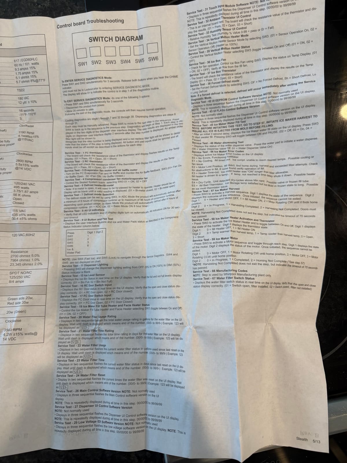
Entering service diagnostic mode
- Make sure the dispenser isn't in Lockout.
- Press SW1 and SW2 together for 3 seconds. Let go when you hear the chime.
- The display shows 01, which means you're on step 1.
The sheet numbers the dispenser buttons SW1 to SW6 and names SW4 as Fast Ice and SW5 as Lock. On this control, counting the buttons left to right gives SW1 = Ice/Water, SW2 = Light, SW3 = Temp, SW4 = Fast Ice, SW5 = Lock, SW6 = Filter Status.
Moving between steps
- SW5 (Lock) goes to the next step, SW4 (Fast Ice) goes back one.
- The step number shows first with the amber filter light on. About 2 seconds later the result shows with the red replace filter light on.
- Cooling tests are steps 1 to 7 and 32 to 39. Dispensing tests are steps 8 to 31.
- Unless a step says otherwise, buttons and pads are ignored and all loads are off.
Exiting
Do one of these: press SW1 and SW2 together for 3 seconds, unplug the fridge, or wait 20 minutes. The controls then go back to normal operation.
Service test steps
| Step | Test | What it shows / does |
|---|---|---|
| 1 | Freezer (FC) thermistor | 01 = pass, 02 = open, 03 = short |
| 2 | Refrigerator (RC) thermistor | 01 = pass, 02 = open, 03 = short |
| 3 | Freezer evaporator fan and air baffle | SW3 toggles. 01 = fan on, baffle open; 02 = fan on, baffle closed |
| 4 | Compressor, condenser fan, evaporator fan | SW3 toggles the sealed system loads. 01 = on, 02 = off |
| 6 | Defrost heater / bi-metal | 01 = bi-metal closed, 02 = bi-metal open. If the bi-metal is open, it has to be bypassed for the heater to run. Display stays blank until a valid reading |
| 7 | Defrost mode selection | SW3 selects. 01 = ADC (adaptive) mode, defrosts after 8 to 96 hours of compressor run time; 02 = basic mode, every 8 hours |
| 8 | All UI indicators | All lights and display digits on for 30 seconds |
| 9 | UI buttons and pads | Shows which button or pad is pressed (SW1 = 1, SW2 = 2, SW3 = 3, SW6 = 6, ice and water pad = 1 on digit 2) |
| 11 | Dispenser lighting | SW3 steps off / on (100%) / dim (50%) |
| 15 | Ice level sensor | 01 = bin full, 02 = bin not full |
| 16 | Refrigerator door switch | 01 = door open, 02 = door closed |
| 17 | Freezer door switch | 01 = door open, 02 = door closed |
| 19 | Ice maker fill tube heater and facia heater | SW3 toggles. 01 = on, 02 = off |
| 20 | Water filter usage rating | Rated gallons, shown in two flashes (123 shows as 12, then 3-) |
| 21 | Water filter time rating | Rated days, two flashes |
| 22 | Water filter usage | Gallons since last reset, two flashes |
| 23 | Water filter time | Days since last reset, two flashes |
| 24 | Water filter reset count | Times the filter was reset, two flashes |
| 26 | Main control software version | Three flashes, 00/00/00 to 99/99/99 |
| 27 | Dispenser UI software version | Not normally used |
| 29 | Low voltage IDI software version | Not normally used |
| 31 | Touch input module software version | Not normally used |
| 32 | Ambient thermistor (UI control) | 01 = pass, 02 = open, 03 = short |
| 33 | Humidity sensor (UI control) | 0 to 99 = pass, Er = fail |
| 34 | Vertical mullion heater mode | SW3 selects. 01 = sensor operation on, 02 = sensor off (heater on 100%) |
| 35 | Vertical mullion heater status | SW3 toggles. 01 = on, 02 = off |
| 36 | Ice box fan | SW3 toggles. 01 = on, 02 = off. Check for airflow from the fan |
| 37 | Ice box thermistor | 01 = pass, 02 = open, 03 = short |
| 38 | Forced defrost | SW3 selects. OF = none, Sh = short defrost, Lo = long defrost. Defrost starts as soon as you exit service mode |
| 42 | UI EEPROM software version | Not normally used |
| 43 | UI flash software version | Not normally used |
| 45 | Ice maker water fill | Run step 57 first so the mold is empty. SW3 toggles fill. 02 = off, 03 = on, 04 = paused |
| 46 | Water dispensing | Press the water pad. 00 = valve off, 01 = valve on |
| 56 | Ice maker error codes | See the table below |
| 57 | Ice maker harvest | SW3 starts a harvest. Digit 1: 0 = heater and motor off, 1 = heater on, 2 = motor turning to home. Digit 2: 0 = in progress, 1 = done, 2 = not completed. Doors must be closed |
| 58 | Ice maker heater and thermistor | SW3 toggles the heater. Digit 1: 0 = off, 1 = on. Digit 2: 0 = warmer than harvest temp, 1 = cooler, 2 = open, 3 = short |
| 59 | Ice maker motor | SW3 steps the motor. Digit 1: 0 = off, 1 = clockwise to home, 2 = off, 3 = counterclockwise to home. Digit 2: 0 = in progress, 1 = done, 2 = homing not complete |
| 66 | Manufacturing codes | Factory use only |
| 67 | Water filter switch | 01 = switch open (filter installed), 02 = switch closed (no filter) |
Ice maker error codes (step 56)
| Code | Meaning |
|---|---|
| E0 | No errors, ice maker working |
| E1 | No cooling. The ice compartment couldn't reach temperature. Look at cooling or fan problems |
| E2 | Motor lost position. It didn't find home during harvest. Check for something blocking the ice maker, then the ice maker itself |
| E3 | Heater time-out. The mold heater ran longer than allowed without reaching temperature. Possible heater problem |
| E4 | Dry cycle. Possible water valve problem or frozen fill tube |
| E5 | Bad ice maker thermistor. Bin is satisfied but the mold stays frozen too long |
Component specifications
All parts 115 VAC, 60 Hz unless noted.
| Part | Spec |
|---|---|
| Compressor | EGD60HLC, 617 BTU/h, 101 W. Locked rotor 9.3 A, full load 1.75 A (±15%). Run winding 5.1 Ω (±15%), start winding 5.7 Ω (±8%) at 77°F |
| Start relay | TSD2 |
| Run capacitor | 12 µF ±10%, 180 VAC |
| Electric damper | 16 seconds max closing time, rated -11°F to 110°F, 3 RPM |
| Condenser fan motor | Clockwise (facing the end opposite the shaft), 1190 RPM, 4.1 W ±15% at 115 VAC |
| Freezer evaporator fan motor | Clockwise, 2800 RPM, 5.5 W ±15% at 14 VDC |
| Defrost bi-metal (thermostat) | Opens above 42°F ±5°, closes below 12°F ±7° |
| Freezer defrost heater | 115 VAC, 435 W ±5%, 30.4 Ω ±5% |
| Thermistors | 2,700 Ω at 77°F (±5%), 7,964 Ω at 32°F (±1%), 23,345 Ω at 0°F (±2%) |
| Control board | 120 VAC, 60 Hz |
| Light switch | SPDT NO/NC, 125/250 VAC, 8/4 A |
| Dual water valve | Green side 20 W, red side 35 W |
| Isolation valve | 20 W (green) |
| Ice box fan | Clockwise, 3500 RPM, 4.2 W ±15% at 14 VDC |
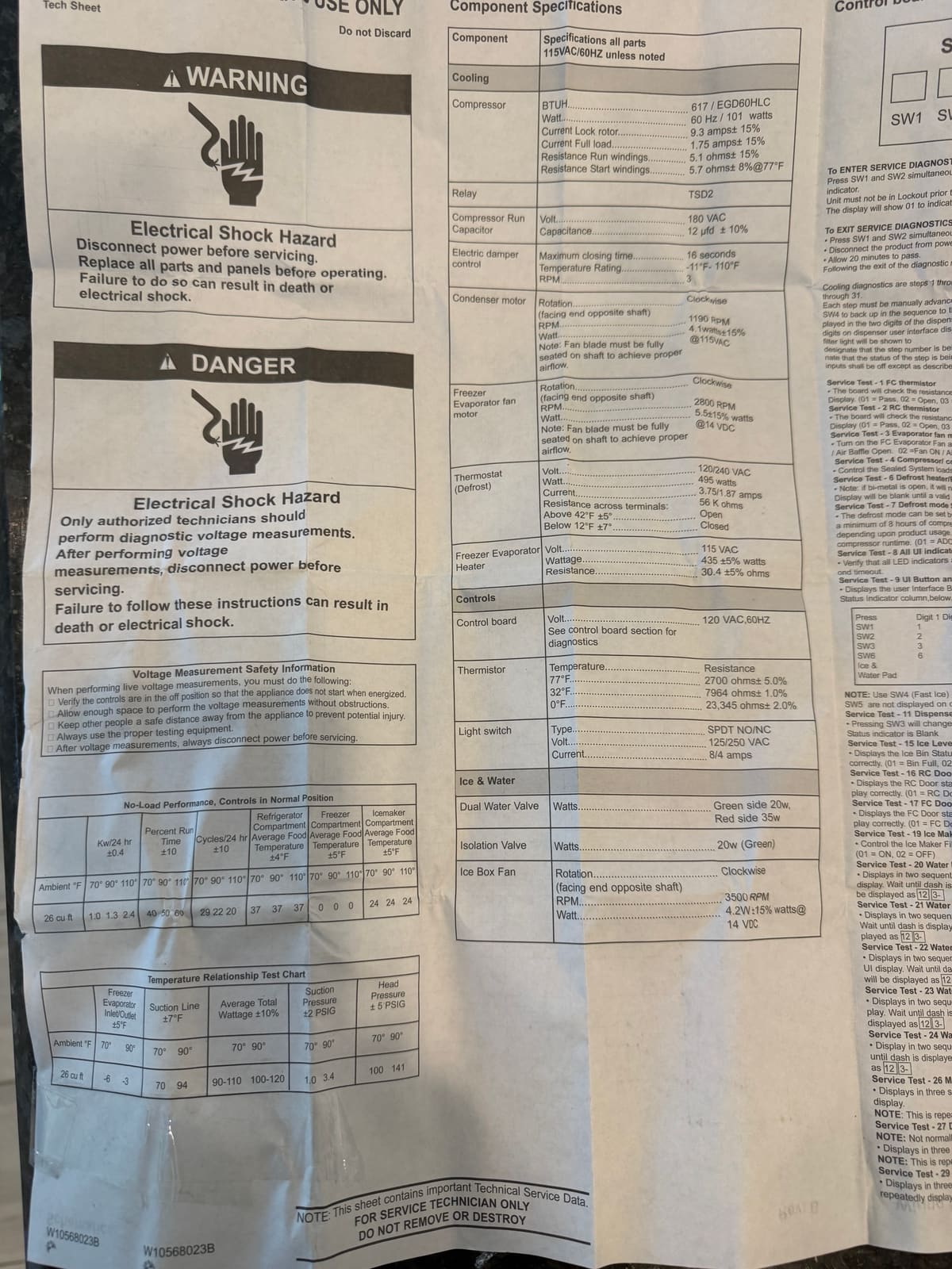
No-load performance (26 cu ft, controls in normal position)
| Room temperature | 70°F | 90°F | 110°F |
|---|---|---|---|
| kWh per 24 hr (±0.4) | 1.0 | 1.3 | 2.4 |
| Percent run time (±10) | 40 | 50 | 60 |
| Cycles per 24 hr (±10) | 29 | 22 | 20 |
| Fridge average food temp, °F (±4) | 37 | 37 | 37 |
| Freezer average food temp, °F (±5) | 0 | 0 | 0 |
| Ice maker compartment temp, °F (±5) | 24 | 24 | 24 |
Sealed system temperature relationship (26 cu ft, R134a)
| Room temperature | 70°F | 90°F |
|---|---|---|
| Freezer evaporator inlet/outlet, °F (±5) | -6 | -3 |
| Suction line, °F (±7) | 70 | 94 |
| Average total wattage (±10%) | 90 to 110 | 100 to 120 |
| Suction pressure, PSIG (±2) | 1.0 | 3.4 |
| Head pressure, PSIG (±5) | 100 | 141 |
Rather have someone else run the tests? We repair Whirlpool refrigerators around Palm Harbor, Oldsmar, Clearwater and nearby. See our refrigerator repair page or call (727) 599-9631.