Frigidaire Affinity Electric Dryer Diagnostic Mode and Error Codes
We typed this up from the dryer tech data sheet (number 137507300A, dated 1111) that came with a Frigidaire Affinity electric dryer, model FASE7073NW0, during anE64 heater repair in Tarpon Springs. The sheet covers both electric and gas models, and we've kept the notes for electric. Other dryers on the same platform may use a similar sheet, but check the one that came with yours.
This is service technician information. The sheet says to disconnect electrical current before servicing, and some diagnostic steps run the motor and heaters. If you're not comfortable with that, call a technician.
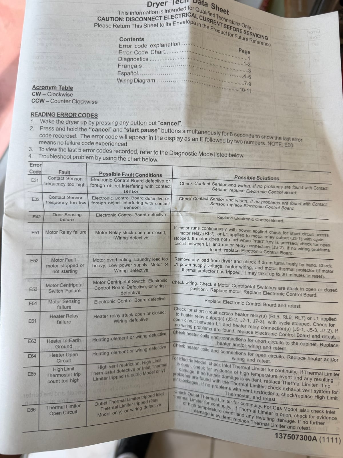
Reading error codes
- Wake the dryer by pressing any button except Cancel.
- Press and hold Cancel and Start/Pause together for 6 seconds. The last error code recorded shows as an E followed by two numbers. E00 means no failure code was recorded.
- To see the last 5 error codes, use diagnostic mode below.
- Troubleshoot with the error code chart further down.
Factory reset
Press and hold the Temperature and Dry Level buttons together for 6 seconds. On models with Temperature, Dry Level and Dry Time buttons, press and hold Dry Level and Dry Time together for 6 seconds.
Entering diagnostic mode
- Press Cancel to put the dryer in standby and enable diagnostic entry.
- Within 10 seconds after pressing Cancel, press any button except Cancel to wake the control.
- Within 5 seconds of waking it up, turn the selector knob to the far left cycle, then press and hold Cancel and the center button under the display together for 3 seconds. The sheet notes you can skip the welcome screen by turning the selector knob.
- On entering, all lights flash on and off.
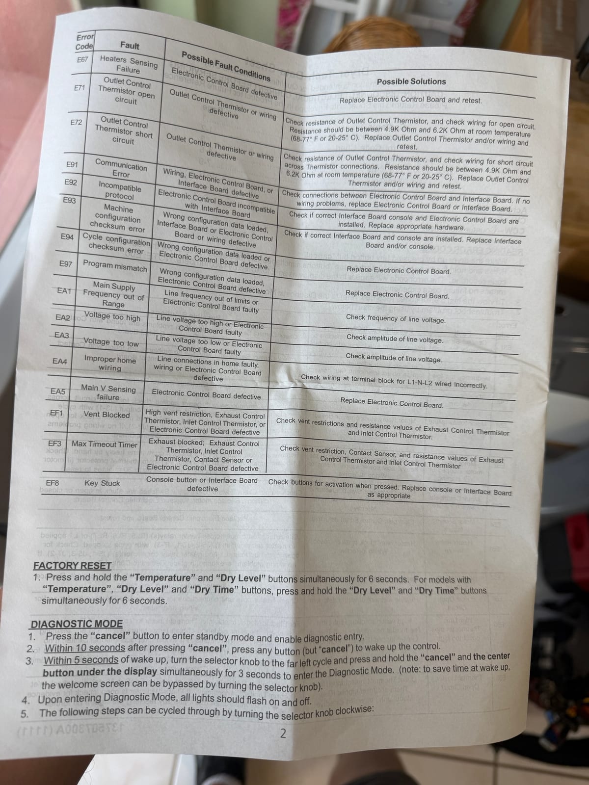
- Turn the selector knob clockwise to step through the diagnostic positions below.
Diagnostic steps
The sheet's table lists the selector position, what's activated, what to check, and what the display shows. On gas models the heater steps run a single heater (and step 4 also fires the igniter); the table below follows the electric column.
| Position | Tested / activated | What to check | Display |
|---|---|---|---|
| 0 | Lights / buttons test | ||
| 1 | Motor clockwise | Check motor function. Look for the drum turning clockwise. | MOTOR CW |
| 2 | Contact sensor | Check the moisture reading. Put your fingers across the contact sensor and watch the digits change from 1111 to 8888. 1111 means the contact sensor is an open circuit. 8888 means it's shorted. | MOIST. BARS |
| 3 | Motor clockwise | Check motor function. Look for the drum turning clockwise. | MOTOR CW |
| 4 | Lights / buttons test and motor clockwise | Check all buttons and lights. Press every button and listen for a beep and a button ID number in the digit display. Check that all lights work. | Digits show the button ID number |
| 5 | Motor clockwise and heater 1 | Check motor and heater function. Check the outlet control thermistor value in the digit display. | HEAT1 - NTC1. Digits: outlet control thermistor value (°F) |
| 6 | Motor clockwise, heater 1 and heater 2 | Check motor and heater function. | HEAT2 - NTC2. Digits: inlet control thermistor value (°F) |
| 7 | Motor clockwise, heater 1, 2 and 3 | Check motor and heater function. Check the outlet control thermistor value in the digit display. | HEAT3 - NTC1. Digits: outlet control thermistor value (°F) |
| 8 | Motor clockwise | Check for mist. | MIST VALVE |
| 9 | Error code history | Shows the last 5 error codes. | Digits show the error code |
| 10 | Software version | Shows the software version. | Software version |
To clear the error codes, press and hold the center key under the display and Cancel together for 3 seconds.
Leaving diagnostic mode
- Unplug the power cord, wait 5 to 8 seconds, then plug it back in, or
- Turn the program knob to the Start position (lights/buttons test), then press Cancel and the center button under the display together for 6 seconds.
Error code chart
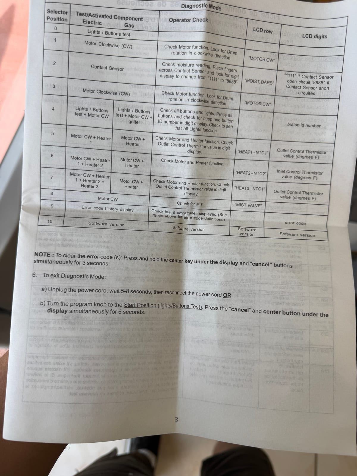
This is our summary of the sheet's chart: the fault, the possible conditions, and what the sheet tells the technician to do. "Electronic control board" is the main board.
| Code | Fault | Possible conditions | What to do |
|---|---|---|---|
| E31 | Contact sensor frequency too high | Electronic control board defective, or a foreign object interfering with the contact sensor. | Check the contact sensor and wiring. If no problems are found with the sensor, replace the electronic control board. |
| E32 | Contact sensor frequency too low | Electronic control board defective, or a foreign object interfering with the contact sensor. | Check the contact sensor and wiring. If no problems are found with the sensor, replace the electronic control board. |
| E42 | Door sensing failure | Electronic control board defective. | Replace the electronic control board. |
| E51 | Motor relay failure | Motor relay stuck open or closed; wiring defective. | If the motor runs continuously with power applied, check for a short circuit across the motor relay (RL2), or L1 applied to the motor relay output (J3-1) with the cycle stopped. If the motor doesn't start when Start is pressed, check for an open circuit between L1 and the motor relay connection (J3-2). If no wiring problems are found, replace the electronic control board. |
| E52 | Motor fault: motor stopped or not starting | Motor overheating; laundry load too heavy; low power supply; motor or wiring defective. | Remove any load from the dryer and check if the drum turns freely by hand. Check the L1 power supply voltage, the motor wiring and the motor thermal protector. If the thermal protector has tripped, it may take up to 30 minutes to reset. |
| E53 | Motor centrifugal switch failure | Motor centrifugal switch, electronic control board or wiring defective. (The sheet spells it "centripetal".) | Check wiring. Check if the motor centrifugal switches are stuck in open or closed positions. Replace the motor. Replace the electronic control board. |
| E54 | Motor sensing failure | Electronic control board defective. | Replace the electronic control board and retest. |
| E61 | Heater relay failure | Heater relay stuck open or closed; wiring defective. | Check for a short circuit across the heater relays (RL5, RL6, RL7), or L1 applied to the heater relay outputs (J5-2, J7-1, J7-3) with the cycle stopped. Check for an open circuit between L1 and the heater relay connections (J5-1, J5-3, J7-2). If no wiring problems are found, replace the electronic control board and retest. |
| E63 | Heater to earth ground | Heating element or wiring defective. | Check the heater coils and connections for short circuits to the cabinet. Replace the heater and/or wiring and retest. |
| E64 | Heater open circuit | Heating element or wiring defective. | Check the heater coils and connections for open circuits. Replace the heater and/or wiring and retest. |
| E65 | High limit thermostat trip count too high | High vent restriction, high limit thermostat defective, or inlet thermal limiter tripped (electric model only). | On an electric model, check the inlet thermal limiter for continuity. If it's open, check for evidence of a high temperature event and any damage. If there's no further damage, replace the thermal limiter. If the limiter is fine, check the exhaust vent system for air blockages. If the vent is clear, check or replace the high limit thermostat and retest. |
| E66 | Thermal limiter open circuit | Outlet thermal limiter tripped; inlet thermal limiter tripped (gas model only) or wiring defective. | Check the outlet thermal limiter for continuity. On a gas model, also check the inlet thermal limiter. If a limiter is open, check for evidence of a high temperature event and any damage. If there's no further damage, replace the thermal limiter and retest. |
| E67 | Heaters sensing failure | Electronic control board defective. | Replace the electronic control board and retest. |
| E71 | Outlet control thermistor open circuit | Outlet control thermistor or wiring defective. | Check the thermistor resistance and the wiring for an open circuit. Resistance should be between 4.9K and 6.2K ohms at room temperature (68 to 77°F, 20 to 25°C). Replace the thermistor and/or wiring and retest. |
| E72 | Outlet control thermistor short circuit | Outlet control thermistor or wiring defective. | Check the thermistor resistance and the wiring for a short circuit across the thermistor connections. Resistance should be between 4.9K and 6.2K ohms at room temperature (68 to 77°F, 20 to 25°C). Replace the thermistor and/or wiring and retest. |
| E91 | Communication error | Wiring, electronic control board or interface board defective. | Check the connections between the electronic control board and the interface board. If there are no wiring problems, replace the electronic control board or the interface board. |
| E92 | Incompatible protocol | Electronic control board incompatible with the interface board. | Check that the correct interface board console and electronic control board are installed. Replace the appropriate hardware. |
| E93 | Machine configuration checksum error | Wrong configuration data loaded; interface board, electronic control board or wiring defective. | Check that the correct interface board and console are installed. Replace the interface board and/or console. |
| E94 | Cycle configuration checksum error | Wrong configuration data loaded, or electronic control board defective. | Replace the electronic control board. |
| E97 | Program mismatch | Wrong configuration data loaded; electronic control board defective. | Replace the electronic control board. |
| EA1 | Main supply frequency out of range | Line frequency out of limits, or electronic control board faulty. | Check the frequency of the line voltage. |
| EA2 | Voltage too high | Line voltage too high, or electronic control board faulty. | Check the amplitude of the line voltage. |
| EA3 | Voltage too low | Line voltage too low, or electronic control board faulty. | Check the amplitude of the line voltage. |
| EA4 | Improper home wiring | Line connections in the home faulty; wiring or electronic control board defective. | Check the wiring at the terminal block for L1-N-L2 wired incorrectly. |
| EA5 | Main V sensing failure | Electronic control board defective. | Replace the electronic control board. |
| EF1 | Vent blocked | High vent restriction; exhaust control thermistor, inlet control thermistor or electronic control board defective. | Check vent restrictions and the resistance values of the exhaust control thermistor and the inlet control thermistor. |
| EF3 | Max timeout timer | Exhaust blocked; exhaust control thermistor, inlet control thermistor, contact sensor or electronic control board defective. | Check vent restriction, the contact sensor, and the resistance values of the exhaust control thermistor and the inlet control thermistor. |
| EF8 | Key stuck | Console button or interface board defective. | Check the buttons for activation when pressed. Replace the console or the interface board as appropriate. |
Rather have someone else run the tests? We repair dryers around Tarpon Springs, Palm Harbor, Oldsmar and nearby. See our dryer repair page or call(727) 599-9631.